The auxiliary arm rarely gets the attention it deserves when people evaluate a wheel loader, yet it shapes how well the machine lifts, digs, and handles attachments. Every ounce of hydraulic power the loader produces has to travel through this arm before it reaches the work. If the arm is well engineered, that power arrives efficiently and predictably. If it isn't, the hydraulics work harder than they should, and performance suffers. This post explains what the auxiliary arm actually does, how its geometry and cylinder placement influence hydraulic force, why balanced design improves efficiency, and how to match arm configurations to the jobs you run most often.
What Is an Auxiliary Arm on a Wheel Loader?
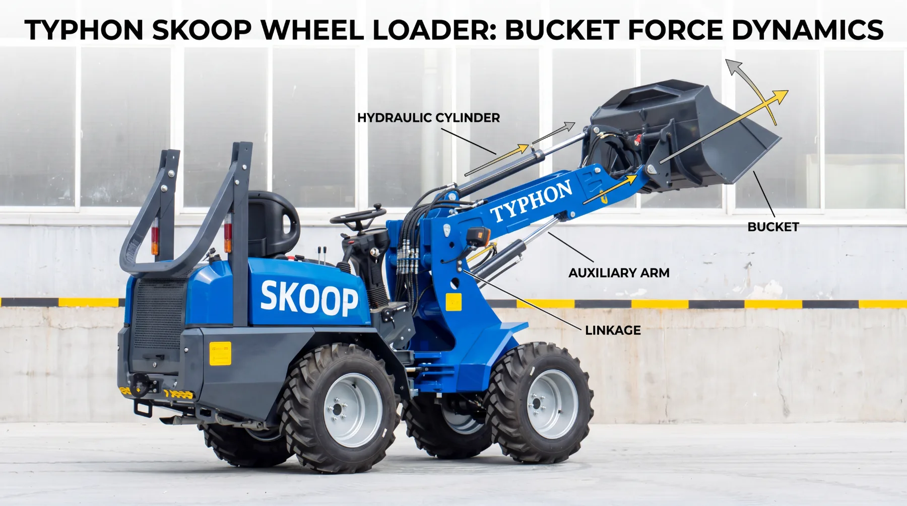
The auxiliary arm is the lifting and linkage component that connects the wheel loader's body to its attachments. Working directly with the hydraulic system, it raises, lowers, and positions buckets, forks, grapples, and other tools throughout the working range. Think of it as the bridge between the machine's hydraulic muscle and the task in front of it. Without a properly designed arm, even a powerful hydraulic system struggles to put its force where it counts.
Its role goes beyond simply holding an attachment. The arm and its linkage translate the push and pull of hydraulic cylinders into controlled, useful motion. As the cylinders extend and retract, the arm converts that linear movement into the lifting and tilting actions operators rely on all day. This conversion is where design begins to matter, because the arm's shape and structure decide how cleanly that force transfers.
The design of the auxiliary arm directly affects how hydraulic force reaches the attachment during operation. A thoughtfully built arm delivers strong, steady force across the full range of motion, from ground level to full lift height. A poorly matched arm, by contrast, can waste hydraulic effort, create uneven movement, or limit how much the loader can safely handle.
Several elements shape how the arm performs its job:
- Structural strength: the arm must resist bending and flexing under heavy loads
- Linkage layout: the arrangement of pivot points governs how motion is produced
- Force transfer: the design decides how much cylinder power reaches the attachment
Understanding the auxiliary arm as an active partner to the hydraulic system, rather than a passive metal frame, is the first step toward appreciating why its design carries so much weight in overall machine performance.
How Arm Geometry Affects Hydraulic Force
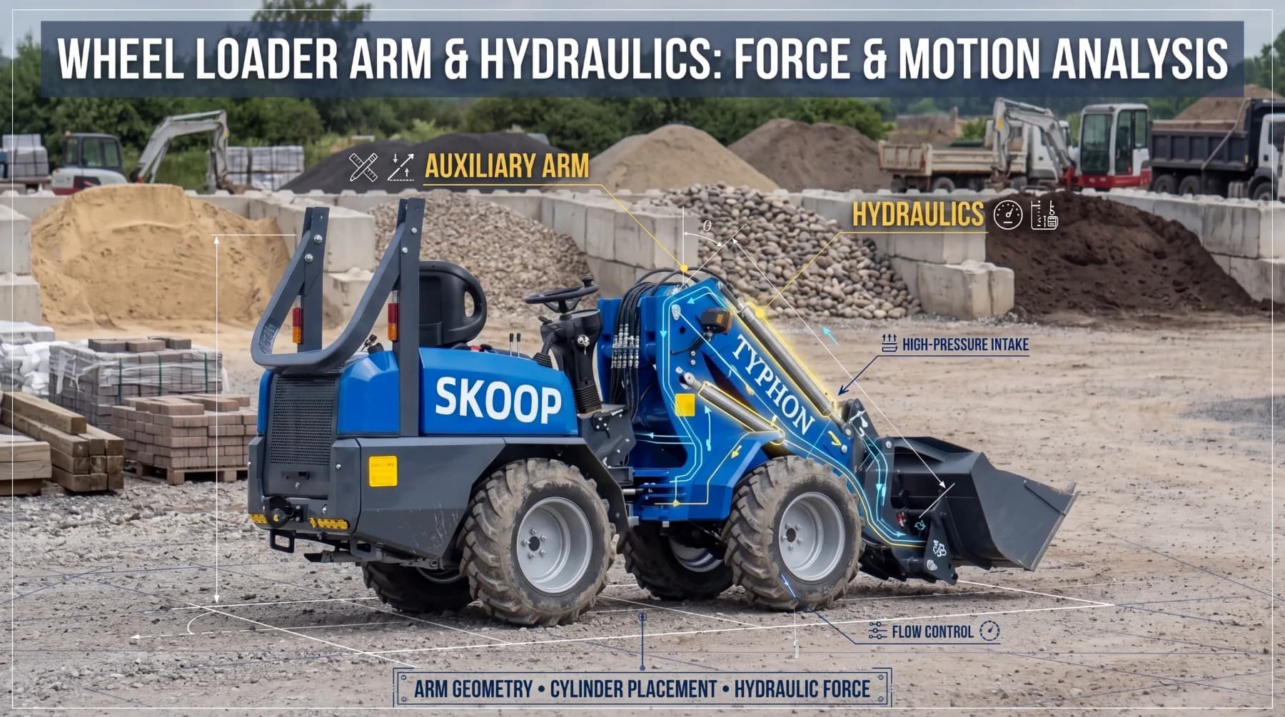
Arm geometry is where engineering decisions turn into real lifting capability. The length, angle, and linkage geometry of the auxiliary arm all influence leverage and the cylinder force required to move a load. Because a wheel loader operates through leverage, small changes in geometry can produce large differences in how much hydraulic effort a given lift demands. Getting the geometry right means the hydraulic system delivers power efficiently rather than fighting against its own design.
Length plays a central role in this relationship. A longer arm can reach higher and farther, but it also increases the leverage acting against the cylinders, which raises the force needed to lift the same load. A shorter arm reduces that demand but sacrifices reach. The angle of the arm at any given moment matters just as much, since the mechanical advantage shifts as the arm rises and falls. A well-designed arm maintains useful force across the entire arc rather than only at one favorable position.
Linkage geometry ties these factors together. The placement and arrangement of pivot points determine how cylinder movement translates into arm motion, and a smart linkage keeps the mechanical advantage strong throughout the working range. This is why two loaders with similar hydraulic pressure can perform very differently; the one with better geometry uses its force more effectively.
Consider how geometry shapes hydraulic demand:
- Arm length: longer arms extend reach but increase required cylinder force
- Working angle: mechanical advantage changes as the arm moves through its arc
- Linkage design: pivot placement governs how efficiently motion is produced
A well-designed arm helps the hydraulic system deliver lifting power efficiently from the ground to full height. When geometry is optimized, the loader lifts more with less hydraulic strain, protecting both performance and the longevity of the hydraulic components.
Hydraulic Cylinder Placement and Performance
Where the hydraulic cylinders sit, and at what angle they mount, has a direct effect on how well they move the auxiliary arm. Cylinder placement determines the leverage the hydraulics can apply, and even a strong cylinder delivers disappointing results if it pushes from a poor position. Proper placement lets the hydraulic system convert its pressure into meaningful lifting and tilting force, which is why manufacturers pay close attention to cylinder positioning during design.
The mounting angle is especially important. When a cylinder acts on the arm at an efficient angle, more of its force contributes directly to useful motion. When the angle is poor, a portion of that force is wasted pushing in a direction that doesn't help the lift. This is straightforward physics, but its impact on the machine is significant. A well-angled cylinder produces stronger, smoother movement while drawing less from the hydraulic system to accomplish the same task.
Placement also shapes how controlled and precise the arm feels during operation. Cylinders positioned to work in harmony with the arm's geometry give operators finer control over attachment positioning, which matters when placing loads carefully or working in tight spaces. Good placement improves three things operators notice immediately: lifting force, movement control, and how accurately the attachment can be positioned.
Key factors in cylinder placement include:
- Mounting position: where the cylinder connects to the arm and frame
- Acting angle: how directly the cylinder's force translates into motion
- Range coverage: maintaining strong force across the full lift arc
Proper cylinder placement can improve lifting force, movement control, and attachment positioning all at once. When cylinders and arm geometry are engineered as a matched pair, the hydraulic system performs closer to its true potential, giving operators the confidence that the machine will respond predictably under load.
Arm Design and Hydraulic Efficiency
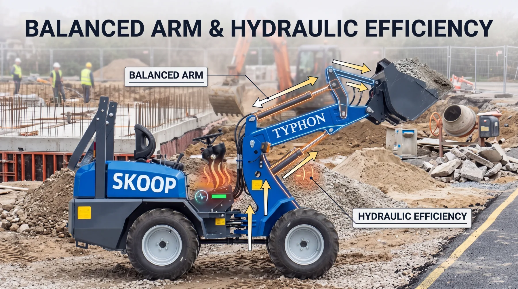
A balanced auxiliary arm design does more than lift loads; it reduces the unnecessary hydraulic demand that drags down efficiency. When the arm's structure, geometry, and cylinder integration work together, the hydraulic system spends less energy overcoming poor mechanical arrangement and more energy doing productive work. This balance is one of the clearest markers of a well-engineered loader, because it shows up in fuel use, responsiveness, and long-term reliability.
Efficiency starts with reducing wasted effort. An unbalanced arm forces the hydraulics to compensate for awkward leverage, uneven weight distribution, or poorly timed motion, all of which increase demand on the pump and cylinders. A balanced design minimizes these losses, allowing the same hydraulic output to accomplish more. Over a full shift, that difference adds up to lower fuel consumption and less heat generated within the hydraulic system.
Smoothness is the other half of the equation. A well-designed arm produces consistent movement across its range, without the surging or hesitation that comes from fighting inefficient geometry. This allows the hydraulic system to operate more efficiently while maintaining smooth and consistent movement, which benefits both the operator and the machine. Predictable motion makes the loader easier to control and reduces the stress placed on hydraulic components over time.
The practical rewards of a balanced design are worth noting:
- Lower demand: the hydraulics work less to achieve the same result
- Reduced heat and wear: efficient motion protects pumps, valves, and cylinders
- Consistent control: smooth movement improves precision and operator confidence
When arm design and hydraulics are properly aligned, efficiency becomes a built-in advantage rather than something operators chase through settings alone. The machine simply works better, running cooler, responding more predictably, and holding up longer under the demands of daily use.
Choosing an Arm Design for Different Applications
No single auxiliary arm design suits every job, which is why matching the arm to the application matters so much. Different tasks place different demands on the loader, and the right arm configuration depends on factors like lifting height, breakout force, attachment type, and the working conditions on site. Choosing well means the loader performs at its best for the work it actually does, rather than compromising across the board.
Lifting height and breakout force often pull in different directions. Jobs that require stacking material high or loading tall trucks benefit from arm designs built for greater reach, while tasks like digging into compacted material or prying loads free demand strong breakout force closer to the ground. An arm optimized for one may sacrifice some capability in the other, so understanding your primary work is essential. Attachment type adds another layer, since a design suited to a standard bucket may not be ideal for forks, grapples, or specialized tools that shift the load center or change how force is applied.
Working conditions round out the decision. Rough terrain, confined spaces, and continuous heavy-duty cycles each favor different design priorities, from durability to precise control. The goal is always to match the arm design with the loader's hydraulic capabilities, so the two work as a coordinated system.
Before settling on a configuration, weigh these considerations:
- Lifting height: taller reach suits stacking and high loading tasks
- Breakout force: strong ground-level force suits digging and prying
- Attachment type: match the arm to the tools you run most often
- Working conditions: account for terrain, space, and duty cycle
Matching arm design with hydraulic capability helps maximize overall machine performance. When the arm suits both the application and the hydraulic system behind it, the loader delivers stronger, more efficient, and more reliable results across the tasks that define your operation.
Conclusion
The auxiliary arm is far more than a structural link between a wheel loader and its attachments; it determines how effectively hydraulic power becomes real work. Its geometry shapes the leverage and cylinder force needed for every lift, while cylinder placement decides how cleanly that force turns into controlled motion. A balanced design reduces unnecessary hydraulic demand, keeps movement smooth, and protects components from excess heat and wear. And because different jobs call for different priorities, matching the arm to your lifting height, breakout force, attachments, and conditions ensures the hydraulic system performs to its full potential. Understand these connections, and you can choose a loader that lifts stronger, runs more efficiently, and holds up reliably day after day.
Frequently Asked Questions
1. What does the auxiliary arm on a wheel loader actually do?
The auxiliary arm is the lifting and linkage component that connects the wheel loader to its attachments, working with the hydraulic system to raise, lower, and position tools. As the hydraulic cylinders extend and retract, the arm converts that linear motion into the lifting and tilting actions operators use throughout the day. In effect, it serves as the bridge between the machine's hydraulic power and the task at hand. Its design directly affects how efficiently and predictably that force reaches the attachment, making it a key contributor to overall performance.
2. How does arm geometry affect hydraulic force?
Arm geometry, including length, angle, and linkage arrangement, determines the leverage acting on the hydraulic cylinders. A longer arm extends reach but increases the cylinder force needed to lift the same load, while the working angle changes the mechanical advantage as the arm moves through its arc. Linkage geometry ties these together by governing how cylinder movement becomes arm motion. A well-designed arm maintains strong, useful force across the full working range, so the hydraulic system delivers lifting power efficiently rather than straining against its own design.
3. Why does hydraulic cylinder placement matter so much?
Cylinder placement and mounting angle decide how effectively the cylinders move the arm. When a cylinder acts on the arm at an efficient angle, more of its force contributes directly to useful motion; a poor angle wastes force in unhelpful directions. Good placement improves lifting force, gives operators finer movement control, and allows more accurate attachment positioning. When cylinders are positioned in harmony with the arm's geometry, the hydraulic system performs closer to its true potential and responds more predictably under load.
4. How does arm design improve hydraulic efficiency?
A balanced arm design reduces the unnecessary hydraulic demand caused by awkward leverage, uneven weight distribution, or poorly timed motion. With less effort wasted, the same hydraulic output accomplishes more, lowering fuel consumption and reducing heat inside the system. A well-designed arm also produces smooth, consistent movement without surging or hesitation, which protects pumps, valves, and cylinders over time. The result is a loader that runs cooler, responds more predictably, and delivers better efficiency as a built-in advantage rather than something chased through settings.
5. How do I choose the right arm design for my application?
Start by identifying your primary work, since lifting height and breakout force often pull in opposite directions. Tall stacking or high loading favors arms built for reach, while digging and prying benefit from strong ground-level breakout force. Consider the attachments you run most, as forks, grapples, and specialized tools change how force is applied. Factor in working conditions like terrain, confined spaces, and duty cycle. Above all, match the arm design to the loader's hydraulic capabilities so the two operate as a coordinated system, maximizing overall performance.